Bradford White Error 4 Error: Pilot Flame Low Voltage / Thermopile Fault
Fix Bradford White gas water heater error 4 (4 flashes - low thermopile voltage).
The electronic gas control valve detects thermopile voltage below the minimum operating threshold (less than 350 millivolts DC under pilot flame).
Probable Causes
Dirty pilot burner orifice or lint-choked flame arrestor reducing pilot flame heat on thermopile.
Degraded thermopile unable to generate required 350–500 mV DC output.
Loose wiring terminal connections on Honeywell gas control valve terminal block.
Diagnostic & Testing Steps
- •Status LED on Honeywell gas control valve blinks 4 times intermittently.
- •Main gas burner fails to light and water stays cold.
- •Pilot flame is weak, orange, or extinguishes immediately after releasing pilot button.
Tools & Equipment Required
- ✓Digital Multimeter (Resistance Mode)Measure high-temperature cutoff (ECO) thermistor resistance (nominal: 10 kΩ at 25°C).
- ✓1/4-inch Hex Nut Driver & FlatheadRemove electronic gas control valve front cover to inspect sensor terminals.
- ✓Needle-Nose PliersDisconnect thermistor wire clip from electronic gas valve control module.
- ✓FlashlightInspect thermal well for limescale deposits causing false overheat readings.
Fast Reset Sequence: Universal 5-Minute Power Isolation Reset
Before unmounting panels or beginning diagnostic procedures, attempt this manufacturer reset to clear transient microcomputer lockouts:
- 1.Press the Power or Cancel button to interrupt the active cycle.
- 2.Completely unplug the appliance or trip the dedicated wall circuit breaker.
- 3.Leave disconnected for 5 minutes to discharge internal power supply capacitors and reset microcontrollers.
- 4.Reconnect power and run a test cycle to confirm whether the error is transient or hardware-related.
- 1
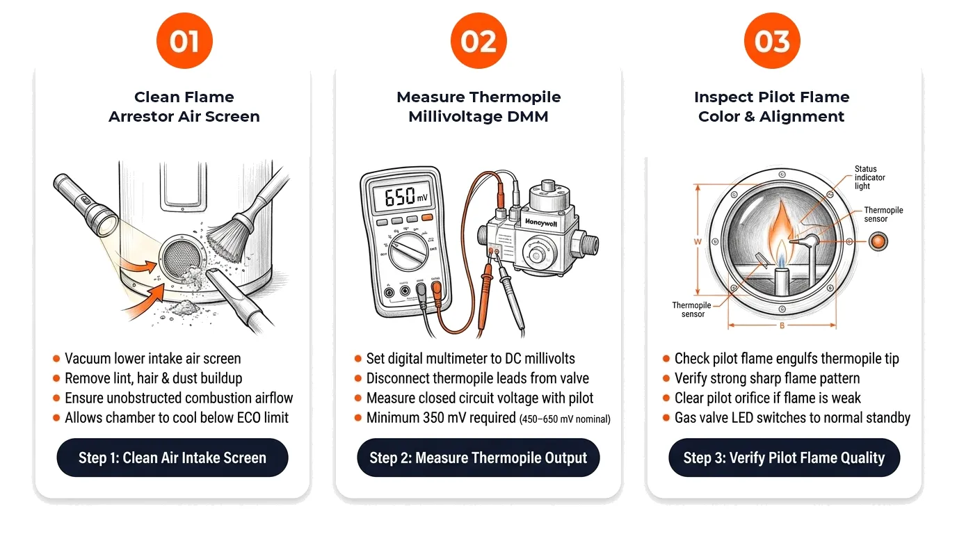
Step 1: Clean Flame Arrestor Air Screen
[ ] DoneInspect air intake screen beneath water heater base for lint, carpet fibers, and dust blocking combustion air.
Verification:Air intake screen is completely clean and clear for maximum pilot airflow. - 2
Step 2: Measure Thermopile Millivoltage with DMM
[ ] DoneSet digital multimeter to DC Millivolts (mV DC) scale, light pilot, and test across thermopile terminal spade leads.
Verification:Thermopile generates at least 350 mV DC under load (and > 650 mV DC open-circuit). - 3
Step 3: Inspect Pilot Flame Color and Alignment
[ ] DoneLook through sight glass to verify pilot flame envelope completely engulfs top 3/8-inch of thermopile tip.
Verification:Pilot flame is crisp blue, steady, and LED switches to normal 1-flash heartbeat.
Repair Solutions
Clean combustion chamber flame arrestor screen using a vacuum and stiff brush.
Measure pilot thermopile millivolts with digital multimeter (minimum 350 mV DC closed-circuit under pilot flame).
Replace pilot assembly bracket (thermopile, pilot tube, spark igniter).
Frequently Asked Questions
What is the difference between a thermocouple and a thermopile?
A thermocouple produces ~30 mV DC for basic valves, while a thermopile combines multiple thermocouples to produce 750 mV DC to power electronic gas valves.
Why does my pilot go out as soon as I let go of the knob?
If the thermopile fails to generate at least 350 millivolts, the internal safety magnet coil drops out and shuts off gas flow.