Panasonic H16 Error: Outdoor Current Transformer (CT) Open Circuit
Resolve Panasonic heat pump error code H16 (CT sensor open).
Current Transformer (CT) defect. The outdoor control board senses 0 amps drawn by the inverter compressor while the drive signal is active, indicating a circuit break.
Probable Causes
Open or burned secondary coil winding on the CT current sensor mounted on the outdoor PCB.
Failed intelligent power module (IPM) or blown inverter bridge IGBT transistor.
Compressor harness unplugged or high electrical resistance at compressor hermetic terminal plug.
Diagnostic & Testing Steps
- •Timer LED flashes continuously on indoor display; remote diagnostic shows code H16.
- •Outdoor compressor makes a brief hum for 2 seconds and trips immediately.
- •Heat pump cannot supply hot water to central underfloor loops or radiators.
Tools & Equipment Required
- ✓Digital Multimeter with Current ClampMeasure compressor Current Transformer (CT) sensor winding resistance (40 - 60 Ω).
- ✓Phillips #2 Screwdriver & 10mm SocketDisassemble outdoor unit side cover to access compressor terminal box.
- ✓Needle-Nose Pliers with Insulated GripsUnplug and inspect CT sensor 2-pin connector on outdoor inverter PCB.
- ✓Small FlashlightInspect compressor harness wiring for thermal discoloration or vibration abrasion.
Fast Reset Sequence: HVAC Microprocessor & Fault Memory Clear
Before unmounting panels or beginning diagnostic procedures, attempt this manufacturer reset to clear transient microcomputer lockouts:
- 1.Isolate electrical power to both indoor wall units and outdoor compressor at the main breaker panel.
- 2.Leave powered down for 10 minutes to allow inverter board microprocessors to dump error registers.
- 3.On remote control, press and hold Cancel or Test button for 5 seconds until the display resets to normal temperature mode.
- 4.Restore power to outdoor unit first, wait 3 minutes for crankcase heater pre-warm, then switch on indoor units.
- 1
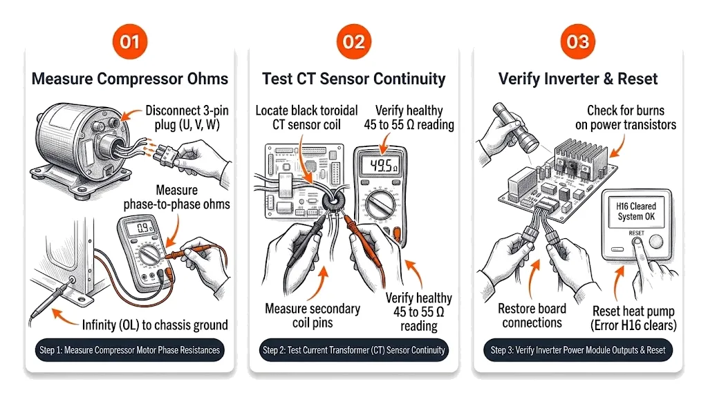
Step 1: Measure Compressor Motor Phase Resistances
[ ] DoneDisconnect 3-pin plug (U, V, W) from compressor terminal and measure phase-to-phase ohms with multimeter.
Verification:All 3 phase combinations read equal resistance within 0.1 Ω; infinity (OL) to chassis ground. - 2
Step 2: Test Current Transformer (CT) Sensor Continuity
[ ] DoneLocate black toroidal CT sensor coil on outdoor circuit board and measure secondary coil pins on 200Ω scale.
Verification:Multimeter confirms healthy reading of 45 to 55 Ω. Infinite resistance indicates an open coil. - 3
Step 3: Verify Inverter Power Module Outputs and Reset
[ ] DoneCheck for visible burns on power transistors, restore board connections, and reset heat pump via user interface.
Verification:Error H16 clears, compressor soft-starts smoothly, and current draw tracks normal ramp-up curves.
Repair Solutions
Measure resistance across the CT sensor secondary pins on the outdoor PCB (nominal 40–60 Ω).
Test compressor motor winding resistance: equal resistance (0.5–1.5 Ω) between U-V, V-W, and W-U.
Replace outdoor power control board if CT sensor or IPM output is burned.
Frequently Asked Questions
Does H16 error mean the compressor is burned out?
Not necessarily. In approximately 70% of cases, H16 is caused by a damaged CT sensor or burned IPM solder joint on the outdoor PCB, while the compressor is physically undamaged.
Can low incoming mains voltage trigger H16?
Yes, if incoming AC voltage sags below 190 VAC during compressor startup, the current transformer waveform will distort and trip an H16 lockout.