Mitsubishi Electric E6 Error: Indoor/Outdoor Communication Error
Diagnose Mitsubishi Electric E6 communication code.
Serial communication failure between indoor fan coil and outdoor condensing unit. Indoor board fails to receive handshake telemetry within 3 minutes of power on.
Probable Causes
Loose, corroded, or miswired terminal connection at terminal 3 (S3) on either unit.
Spliced communication wire with high impedance or water ingress in outdoor disconnect box.
Blown 3.15A glass fuse on outdoor inverter power PCB or fried optocoupler communication chip.
Diagnostic & Testing Steps
- •Indoor unit LED flashes 6 times in sequence; remote control displays E6 code.
- •Indoor blower fan runs but outdoor compressor and condenser fan never start.
- •Air conditioning and heating functions completely inoperative.
Tools & Equipment Required
- ✓Digital Multimeter with Needle ProbesMeasure fluctuating DC serial communication voltage across terminals S2 and S3 (0-24 VDC).
- ✓Slotted 3.5mm Terminal ScrewdriverCheck terminal block screws for loose connections causing signal frame drops.
- ✓Phillips #2 ScrewdriverOpen indoor unit electrical junction box and outdoor control box.
- ✓Wire Stripper & Replacement Fuse PullerInspect and replace 3.15A ceramic communication line fuse on main board.
Fast Reset Sequence: HVAC Microprocessor & Fault Memory Clear
Before unmounting panels or beginning diagnostic procedures, attempt this manufacturer reset to clear transient microcomputer lockouts:
- 1.Isolate electrical power to both indoor wall units and outdoor compressor at the main breaker panel.
- 2.Leave powered down for 10 minutes to allow inverter board microprocessors to dump error registers.
- 3.On remote control, press and hold Cancel or Test button for 5 seconds until the display resets to normal temperature mode.
- 4.Restore power to outdoor unit first, wait 3 minutes for crankcase heater pre-warm, then switch on indoor units.
- 1
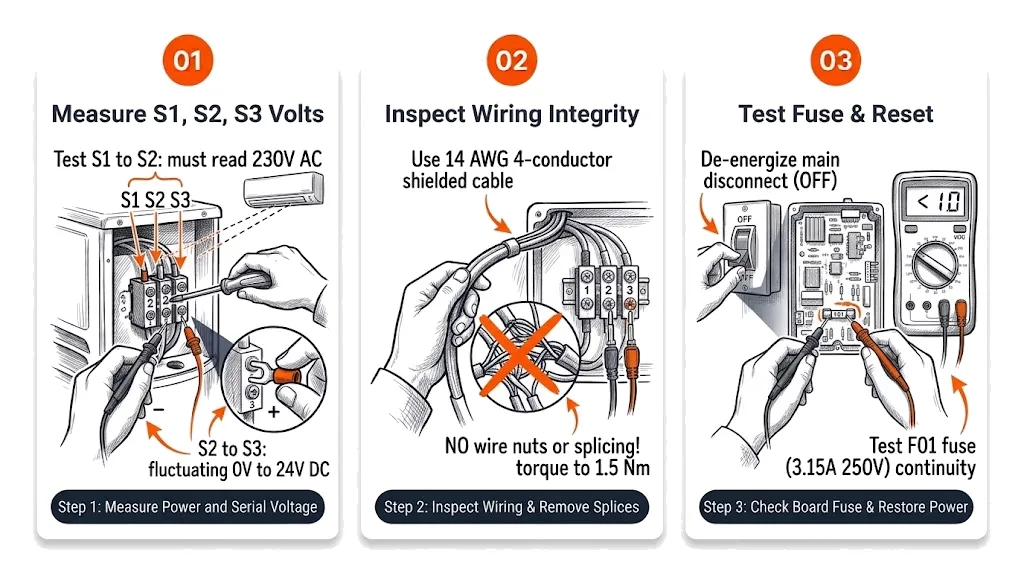
Step 1: Measure Power and Serial Voltage at Terminals S1, S2, S3
[ ] DoneTest AC voltage between S1 and S2 (must read 230VAC). Then test DC voltage between S2 (negative) and S3 (positive).
Verification:S2 to S3 must fluctuate continuously between 0V and 24V DC. A static 0V or 24V indicates a failed communication transceiver. - 2
Step 2: Inspect Wiring Integrity and Eliminate Splicing
[ ] DoneVerify field wiring uses 14 AWG 4-conductor shielded cable without intermediate wire nuts or junction boxes.
Verification:All screw terminals torqued securely to 1.5 Nm with zero oxidation on copper strands. - 3
Step 3: Check Outdoor Board Control Fuse and Reset
[ ] DoneDe-energize main disconnect, remove outdoor PCB cover, and test continuity of fuse F01 (3.15A 250V).
Verification:Fuse has < 1 Ω resistance. Restore power; indoor unit LED stops blinking and compressor ramps up.
Repair Solutions
Measure DC voltage across terminals S2 and S3 with analog or digital multimeter (should pulse actively between 0V and 24V DC).
Verify continuous uninterrupted 14/4 AWG stranded copper wire running between both units.
Inspect outdoor control PCB for blown fuses or electrical surge damage.
Frequently Asked Questions
Can mismatched indoor and outdoor units cause an E6 error?
Yes. Connecting incompatible capacity ratings or mixing non-inverter multi-split components will prevent proper software protocol handshake.
Why does S2-S3 DC voltage fluctuate continuously during normal operation?
The 0-24V DC fluctuation represents digital serial binary data packets transmitting temperature, fan speed, and error telemetry between boards.